Industrial milling has been with us for hundreds of years. The mills have come to be used for a wide variety of activities. For example, him cylinder for milling it is an essential mechanism for the production of food raw materials. Also, for the mechanization of industrial activities and for the generation of energy.
Already the Dutch, during the XII-XIV centuries, had managed to automate many activities and were masters in the use and implementation of mills. In addition, thanks to them they were able to drain liters and liters of water to be able to fight against the sea.
But has the mechanism changed much? What materials are used today? How can we create a milling cylinder?
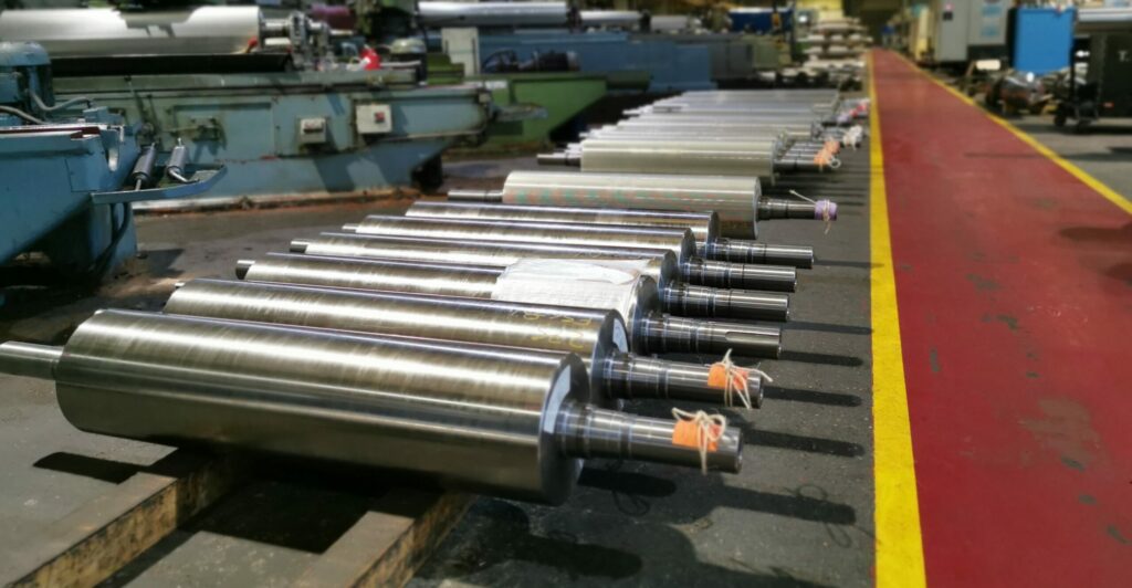
How are these types of cylinders or rollers
First, it is important to note that most rollers and cylinders are made of cast iron or titanium. Also, details such as grooves and entrances stand out, as well as the length and hardness of the cylinder, since these will depend on the activity that is carried out.
Steps to build a cylinder for milling
Manufacturing materials and their application
As we have mentioned before, milling rollers or cylinders are usually made of metals like iron. Obviously, the amount of raw material will not be the same depending on the size of the cylinder. It is not the same to create a cylinder for the mechanism of a fairground attraction than for a refinery or a modern windmill.
However, the most essential step for any application is shaping the material. For this, a centrifugal casting method is used that makes the mold (filled with metals) rotate on the axis of the machine, which will hold the molten metal against the outer wall of the mold. Later, lighter, fine-grained molten material is added to this to absorb shock and enhance the rifling effect. The hardness decrease curve must also be taken into account.
Hardness decrease curve
This curve is represented through a graph to see the increase or decrease in hardness when the axis is in operation. First, mark the parts of the cylinder bases that distribute centrifugal force and determine where it is important to reduce the hardness for optimal traction.
groove design
Grooves are small indentations or cuts in the cylinder rollers that serve to resist shear and compression forces. There are different types of standard grooves that differ in length, cut, apex and back. The cut is the front face of the groove, while the back is the back face and the apex is the point of intersection between the back and the cut. There is a variety of up to 80 shapes
spiral design
The spiral is the slope of the groove. It is used to perform the cutting action and control the effectiveness of grinding. The procedure for drawing the spiral is quite easy; all you need is a pencil and paper. This would be used to measure the depth of the groove, by tracing it onto the paper, which in turn will be resting on the stationary cylinder.